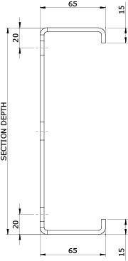
The Duggan Profiles range of Cee sections comprises 7 section depths in either hot-dip (galvanised) material or white prepainted steel.
The galvanised products are available in 1.5, 1.8 and 2mm while the prepainted sections may be supplied in 1.5 or 2mm.
| SECTION RANGE FOR GALVANISED PROSIGMA+ CEE SECTIONS | |||||||
|---|---|---|---|---|---|---|---|
| SECTION DEPTH (MM) | |||||||
| Thickness (mm) | 145 | 175 | 205 | 235 | 265 | 300 | 325 |
| 1.5 | DP-CSG 145/65/150 |
DP-CSG 175/65/150 |
DP-CSG 205/65/150 |
DP-CSG 235/65/150 |
DP-CSG 265/65/150 |
DP-CSG 300/65/150 |
DP-CSG 325/65/150 |
| 1.8 | DP-CSG 145/65/180 |
DP-CSG 175/65/180 |
DP-CSG 205/65/180 |
DP-CSG 235/65/180 |
DP-CSG 265/65/180 |
DP-CSG 300/65/180 |
DP-CSG 325/65/180 |
| 2 | DP-CSG 145/65/200 |
DP-CSG 175/65/200 |
DP-CSG 205/65/200 |
DP-CSG 235/65/200 |
DP-CSG 265/65/200 |
DP-CSG 300/65/200 |
DP-CSG 325/65/200 |
| SECTION RANGE FOR PREPAINTED PROSIGMA+ CEE SECTIONS | |||||||
|---|---|---|---|---|---|---|---|
| SECTION DEPTH (MM) | |||||||
| Thickness (mm) | 145 | 175 | 205 | 235 | 265 | 300 | 325 |
| 1.5 | DP-CSP 145/65/150 |
DP-CSP 175/65/150 |
DP-CSP 205/65/150 |
DP-CSP 235/65/150 |
DP-CSP 265/65/150 |
DP-CSP 300/65/150 |
DP-CSP 325/65/150 |
| 2 | DP-CSP 145/65/200 |
DP-CSP 175/65/200 |
DP-CSP 205/65/200 |
DP-CSP 235/65/200 |
DP-CSP 265/65/200 |
DP-CSP 300/65/200 |
DP-CSP 325/65/200 |
Cee sections are specified by product code. A full list of the codes for the range of sections available is included on the table above.
The codes are defined as per the following examples:
Example 1: DP-CSG205/65/150
DP: Duggan Profiles, used as a prefix for all our sections
CSG: Cee Section Galvanised, this defines the profile and distinguishes it from purlins, rails or Eaves Beams
205: The first 3 digits denote the section depth in mm
65: The second block of digits denotes the flange width in mm
150: The final block of digits denotes the thickness, 150 is 1.5mm, 180 is 1.8mm etc.
Lengths
Duggan Profiles can roll form its cold rolled products in lengths up to 20m. Customers should bear in mind the logistics of transportation and site handling before ordering sections of excessive length. If possible cold rolled sections should not exceed 14m for maximum ease of transportation.
Punching arrangement
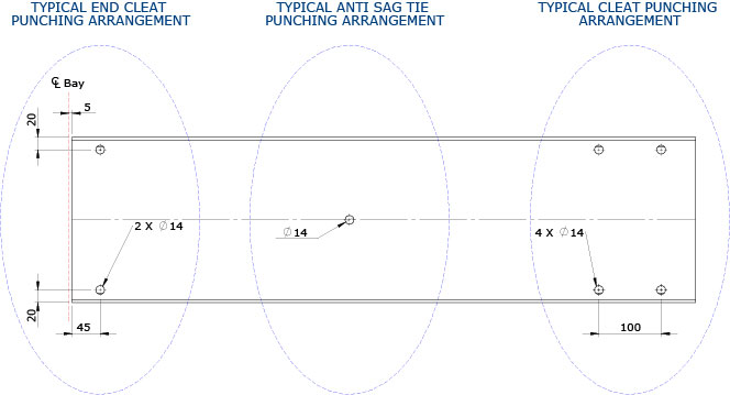
Standard gauge lines for cleat connections are 20mm from top and bottom flanges as shown below. Anti sag ties typically connect to holes on the section centreline. In general all holes are 14mm to suit M12 bolts however 18mm holes are also available if specified. Counterforming along with End Flanging, notching, slotted holes, off standard punching and the provision of service holes are all options available with Cee sections. Refer to ProSigma+ Customisation for more in-depth information on the variety of additional services available.
Material specification (Galvanised)
Purlins, Rails, Eaves Beams and Cee sections from the Duggan Profiles ProSigma range are manufactured as standard from high proof strength steel for cold forming with the following characteristics to EN 10346:2009
Minimum yield strength (Rel): 450MPa
Corrosion protection: Hot-dip zinc coating
Coating designation: Z275
Coating mass: 275g/m2 (The minimum total coating mass both surfaces using triple spot test)
The material thickness is to EN 10143:2006 Continuously hot-dip coated steel sheet and strip. Tolerances on dimensions and shape
Material specification (Prepainted)
Painted Purlins, Rails, Eaves Beams and Cee sections from the Duggan Profiles ProSigma range may be manufactured from organically coated structural steel with the following characteristics:
Steel Name S390
Minimum yield strength: 390MPa
Corrosion protection: Hot-dip zinc coating
Coating designation: Z275
Coating mass: 275g/m2 (The minimum total coating mass both surfaces using triple spot test)
The painted finish to EN 10169:2010 is as follows:
Colour: Chalk White*
A 15μm thick flexible primer specially designed to resist corrosion, applied on both sides.
A 20μm thick flexible chemical and corrosion resistant Polyester Resin finish (Chalk White Top Coat) applied on both sides.
*The colour indicated is for information purposes only. Material samples are the only reliable indicator of colour and are available on request.
The material thickness is to EN 10143:2006 Continuously hot-dip coated steel sheet and strip. Tolerances on dimensions and shape.
SECTION RANGE FOR GALVANISED PROSIGMA+ CEE SECTIONS
Thickness (MM)
1.5mm Thickness:
SECTION DEPTH (MM)
| Thickness (MM) |
145 | 175 | 205 | 235 | 265 | 300 | 325 |
|---|---|---|---|---|---|---|---|
| 1.5 | DP-CSG 145/65/150 |
DP-CSG 175/65/150 |
DP-CSG 205/65/150 |
DP-CSG 235/65/150 |
DP-CSG 265/65/150 |
DP-CSG 300/65/150 |
DP-CSG 325/65/150 |
| PDF: | |||||||
| DXF: |
1.8mm Thickness:
| Thickness (MM) |
145 | 175 | 205 | 235 | 265 | 300 | 325 |
|---|---|---|---|---|---|---|---|
| 1.8 | DP-CSG 145/65/180 |
DP-CSG 175/65/180 |
DP-CSG 205/65/180 |
DP-CSG 235/65/180 |
DP-CSG 265/65/180 |
DP-CSG 300/65/180 |
DP-CSG 325/65/180 |
| PDF: | |||||||
| DXF: |
2.0mm Thickness:
| Thickness (MM) |
145 | 175 | 205 | 235 | 265 | 300 | 325 |
|---|---|---|---|---|---|---|---|
| 2.0 | DP-CSG 145/65/200 |
DP-CSG 175/65/200 |
DP-CSG 205/65/200 |
DP-CSG 235/65/200 |
DP-CSG 265/65/200 |
DP-CSG 300/65/200 |
DP-CSG 325/65/200 |
| PDF: | |||||||
| DXF: |
SECTION RANGE FOR PREPAINTED PROSIGMA+
SECTION DEPTH (MM)
Thickness (MM)
1.5mm Thickness:
| Thickness (MM) |
145 | 175 | 205 | 235 | 265 | 300 | 325 |
|---|---|---|---|---|---|---|---|
| 1.5 | DP-CSP 145/65/150 |
DP-CSP 175/65/150 |
DP-CSP 205/65/150 |
DP-CSP 235/65/150 |
DP-CSP 265/65/150 |
DP-CSP 300/65/150 |
DP-CSP 325/65/150 |
| PDF: | |||||||
| DXF: |
2.0mm Thickness:
| Thickness (MM) |
145 | 175 | 205 | 235 | 265 | 300 | 325 |
|---|---|---|---|---|---|---|---|
| 2.0 | DP-CSP 145/65/200 |
DP-CSP 175/65/200 |
DP-CSP 205/65/200 |
DP-CSP 235/65/200 |
DP-CSP 265/65/200 |
DP-CSP 300/65/200 |
DP-CSP 325/65/200 |
| PDF: | |||||||
| DXF: |
Click on the DXF or PDF icons above to download the CAD (.dxf) or .pdf file.
Trouble downloading?
Right-Click on the DXF icon: this will bring up a menu where you can click on either
‘Save Target As’ or ‘Save Link As’.
Then, after saving the DXF file to your computer you can run your CAD software
and open the DXF file that you saved.
Interpretation of colour used in Visual Aids:
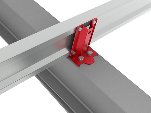
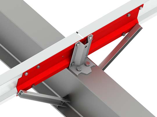
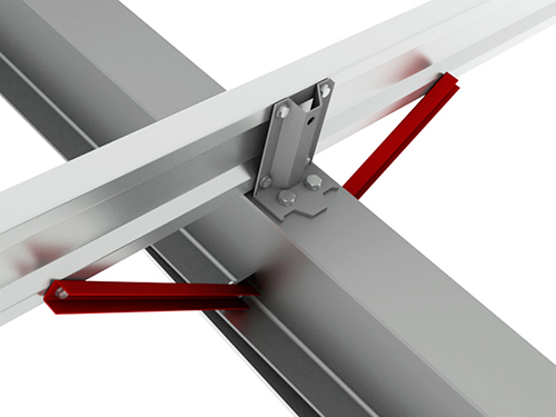
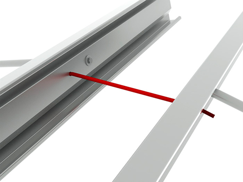
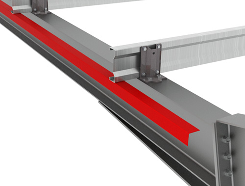
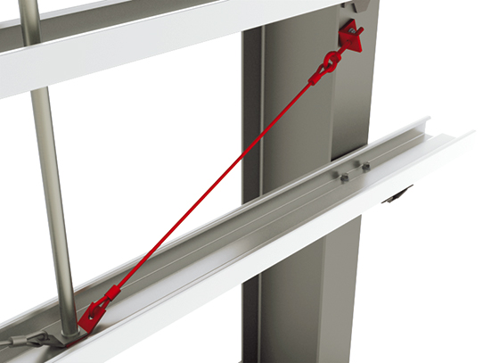
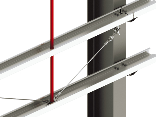
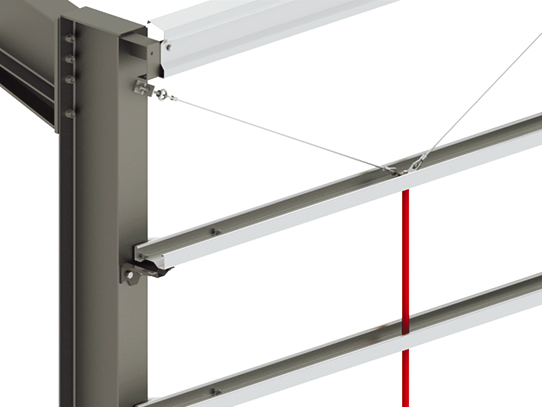
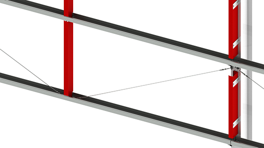
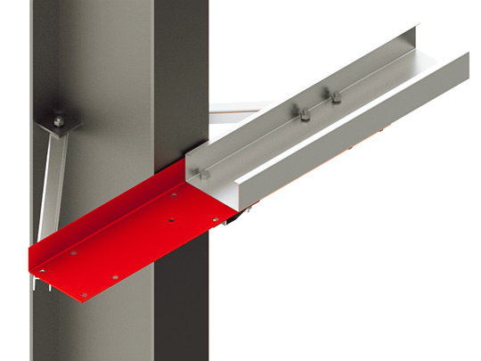
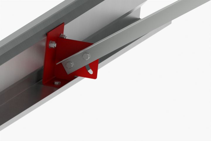
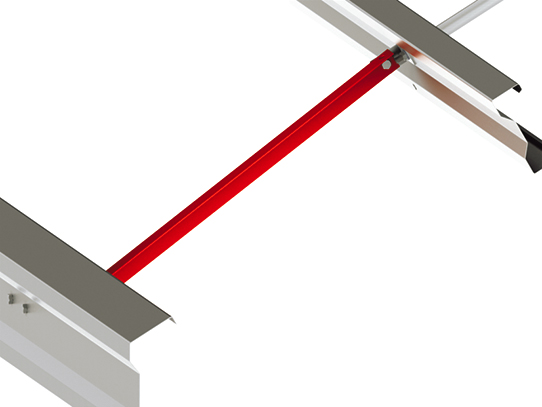
Throughout this section on the Prosigma system extensive use has been made of exaggerated and eye-catching colouring such as red, blue etc. Please note this is used for illustrative purposes only and does not infer that the products in question are supplied in the colours shown. Information on materials and colours available may be obtained from colour charts, material samples and product samples available on request from Duggan Profiles.

STANDARD HOLES
The majority of connections in the Duggan Prosigma system are designed around the use of M12 bolts fitting through 14mm holes. In certain instances where M12 is not deemed adequate M16 bolts fitting through 18mm holes are used (The Eaves Beam Cleat connection to the mainframe is an example). Both 14 & 18mm holes are produced as standard and these may be punched at any position across the width of the blank strip, in other words punching is not limited to standard gauge lines.
SLOTTED HOLES
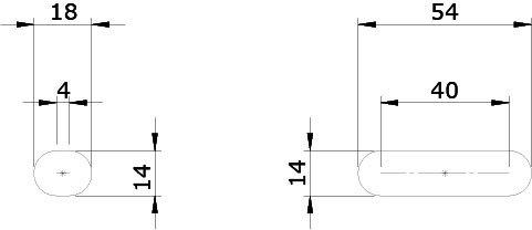
Standard horizontal slot lengths are 14 x 4 and 14 x 40 as shown but any slot length may be achieved using multiple iterations of these punches.
14mm vertical slots may be achieved by nibbling using a series of closely spaced 14mm holes. 18mm slots, both horizontal and vertical may also be produced by nibbling using 18mm round holes. Slots may be punched at any position across the width of the strip.
SERVICE HOLES
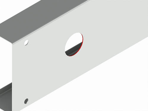
A round 60mm diameter hole may be provided on the centreline of selected sections to accommodate the provision of services such as ducting, pipes, cabling etc. The sections in question include Sigma+ sections of 235 or greater and all Cee sections.
NOTCHING
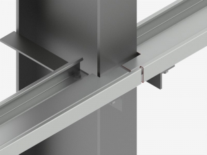
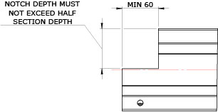
Sigma, Cee and Eaves Beam profiles can be notched. The minimum length of notch is 60mm. A member may be notched from either side or from both, if notching from both sides the depth may be different on either side. The notch must start at the edge of the strip.
End Flanges
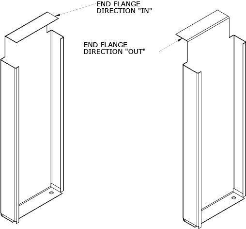
In situations where loading and other factors permit End Flanges may be used instead of cleats/brackets as a cost effective jointing solution. An end flange is formed from the parent material of the member in question by notching the end and folding the remaining tab. The end flange may be punched to allow for a bolted connection or folded unpunched to act as an end closure. Please note end flanges are available on Cee sections only.
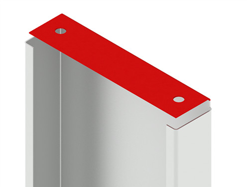
End Flange direction: End Flanges may be formed inward or outward as indicated in the diagrams below. Flanges folded “IN” are the most commonly used type.

COUNTERFORMING
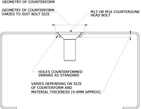
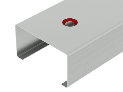
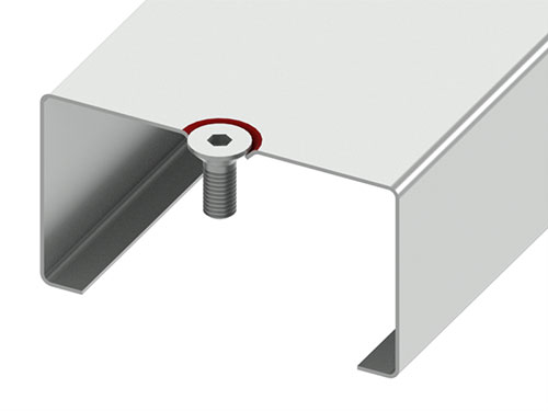
Counterforming of either 14 or 18mm holes may be provided and is generally applicable to Cee sections only. Please contact Duggan Profiles before considering the use of counterformed holes on sections other than Cee’s. The overall depth of the counterform varies with material thickness and should be obtained from samples if critically important. Indicative dimensions are shown on the diagram below.

STRUCAD SUPPORT
Detailing Support for StruCad Users
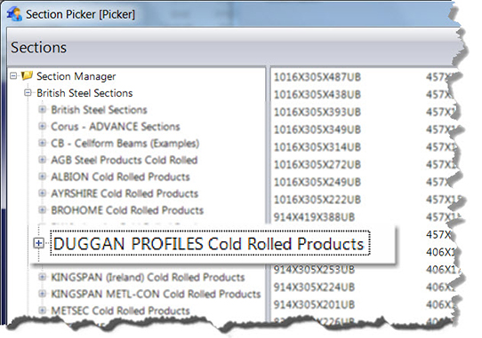
The Duggan Prosigma system is fully intgrated in StruCad. The complete range of Duggan Cold rolled sections is available for detailing from the sections catalogue as shown.
Duggan Connection Macros
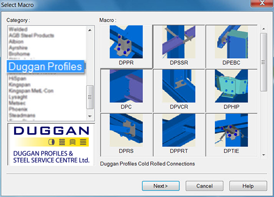
In common with the systems of other manufacturers the Duggan Prosigma installation includes a suite of connection macros which may be accessed as shown below.

Purlin/Rail to Column/Rafter
This creates a cleat connection for both the Sigma and Cee sections. The following options are available:
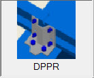
- Prepainted or Galv sections may be used
- The type of Cleat may be defined
- Sleeves may be used
- Rafter Stays may be used
- Firewall slots may be used
- Orientation holes may be added
Simply supported rail to column
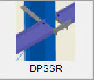 This creates a cleat connection for both the Sigma and Cee sections where the members are inset between columns/rafters.
The following options are available:
- Prepainted or Galv sections may be used
- The type of hot rolled cleat may be defined (Duggan cleats are not suitable)
- Cleats may be slotted
- Members may be Notched around columns
- The inset distance may be varied
Eaves Beam to column
This creates an Eaves Beam cleat connection. The following options are available:
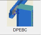
- Prepainted or Galv sections may be used
- Bolt-on or Weld-on cleats may be used
- The stock size may be defined
Note: Duggan Profiles do not supply Eaves Beam Cleats, these must be fabricated as part of the structural steel.
Connections for Cee Sections
This creates a connection between the following:
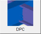
- Cee‘s and other Cee’s
- Cee’s and Eaves Beams
- Cee’s and columns/rafters
The following options are available:
- Prepainted or Galv sections may be used
- End Flanges may be used instead of cleats
- Hot rolled cleats may be used
- Notching may be used
Note: Use the Vertical Cladding Rail macro for connecting Cee’s to Sigma sections.
Vertical Cladding Rail connection
This creates all connections for the Vertical Cladding Rail (VCR). The following options are available:
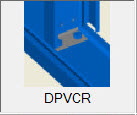
- The horizontal rails may be any type of Sigma or Cee
- The VCR must be a Cee
- Cleat connections to columns may be defined
- Cover channels may be defined and used where required
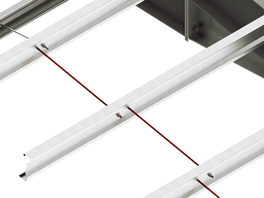
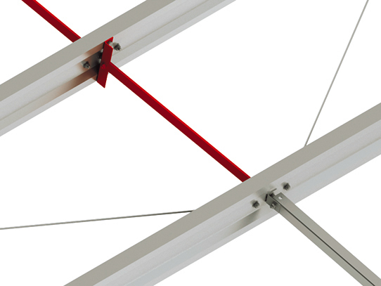
- Tie Ropes may be used
Hip Connection
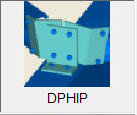 This creates a cleat connection between a Sigma or Cee and a hip rafter. The following options are available:
- The purlins may be any type of Sigma or Cee
- Weld-on or Bolt-on cleats may be used
Note: These cleats must be supplied by the fabricator.
Connection for Eaves Struts & Angle Struts
This creates the end connections for the Eaves Strut and the Angle Strut. These are standard connections and no adjustment is required however the following two connection options for the Eaves Strut are available:
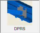
- Eaves Strut connected to purlin web
- Eaves Strut connected to purlin flange
Purlin and Rail Tie connection
This creates the connections for Tube Struts, Tube Ties, Threaded Rod Ties and Apex Ties. It also makes provision for the inclusion of Tie Ropes. The following options are available:
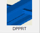
- Sigma or Cee sections may be used
- Any Type of Tube Strut may be used
- Ties may be connected end to end or staggered (Anti sag requirements for Curved Roofs require staggered ties)
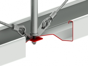
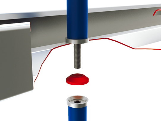
- Counterformed holes with countersunk bolts may be used
Connection for Tie Rope
This connects Tie Ropes with Tube Struts, Tube Ties, Angle Struts and Vertical Cladding Rails (VCR). The following options are available:
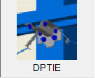
- Sigma or Cee sections may be used as the purlins or rails
- The anchor point at the column/rafter may be adjusted
- The anchor bracket at the column/rafter may be changed
- Tie Ropes can be inset for purlins/rails between rafters/columns
- Counterformed holes with countersunk bolts may be used
Cleader Angle Connection
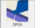 This calculates the length of Cleader Angle required but does not create a connection. Duggan Profiles supply Cleader Angle in 6m lengths for screw fixing on site.
Service Holes
This creates a Service Hole in Sigma sections 235 and deeper and all Cee sections. There are no user defined parameters for this macro and the hole must be applied on the centreline of the section.
How to create an order:
Cold rolled may be ordered from within the StruCad environment by selecting the “Duggan Cam” option on the cold rolled menu.

The dialog box below appears. The order may include everything in the model or may be broken down by Phase, Finish, Prefix etc., in fact Duggan Cam allows ordering of coldrolled based on any user attribute.
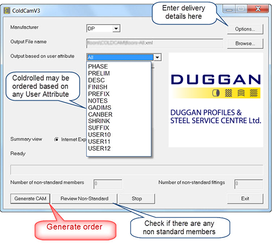
- Choose to order “All” or create the order based on one of the available user attributes.
- Check if there are any non standard items. Items may appear non standard for various reasons such holes not on expected gauge lines or items too long to make. If an item cannot be manufactured it must be edited before ordering. Drawings of non standard items should be included with the order.
- Enter delivery details.
- Click “Generate CAM”.
- Two files are created and saved to the folder you selected (Model directory/COLDCAM/ by default). These two files are “modelname”.asp and “modelname”.xml and they contain the list of non standard items and the order details respectively. Attach these 2 files to an email along with drawings of any non standard items and send them to your normal sales contact. Your order is now placed.


